Here are some tips and info on how to degree cams for the 3SGTE. This article does not cover cam install, just the degreeing process for aftermarket cams. If you do not degree your aftermarket cams, or use the stock cam gears with them, you are seriously cutting down on the power potential and driveability of the cams. Note I use the summit racing degree kit. All instructions are for this kit only. I know for a fact that using a full 360 marked degree wheel will not work with the actual math part of the degreeing process outlined here. The Summit Racing degree wheel goes from 0 to 180, then back down to 0 again.
Remove everything in the way of the valvecover.

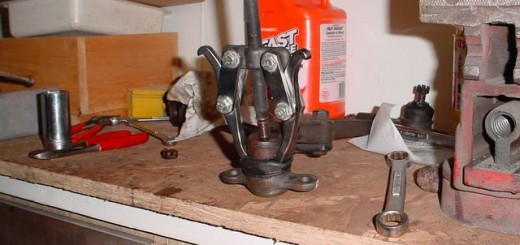
To get the degree wheel on the crank, raise the car, remove the rear wheel, and then you have to remove the pulley bolt. See the pulley bolt tool article for some methods to do this. I’ve had good luck with a breaker bar, and blipping the starter recently. Try that at your own risk though.

Loosely install the degree wheel using washers to keep the center of the wheel from being pulled into the crank pulley by the pulley bolt (that will make more sense once you actually do this part). Install the pointer by securing it to a bolt on the block.

Remove the sparkplugs, and keep towels or rags in the holes to keep debris out. Twice I’ve seen stuff fall in there, and it’s really not fun fishing things out of the cylinders.

Remove the passenger side motor mount. Remove the cam gear cover with a short 10mm socket.


Time to find true “top dead center” of the number 1 piston. There are two ways that I know to do this, I will briefly outline both.
The first is to use a piston stop. Rotate crank to get the #1 piston to the top. The #1 piston is the one closest to the passenger side of the car. You can put a full pencil in the cylinder (no used short ones or it will fall in) to get an idea when it’s near the top. To turn the crank you can either put the car in gear, and turn the rear wheel, or you can tighten down the pulley bolt and turn that. The problem with tightening down the pulley bolt is that one of the next steps is to reset the wheel to true top dead center, and if it’s completely tightened down now, that’s really not going to be possible. Once you raise the piston to the top, rotate the crank counter clockwise 15 degrees. Put the piston stop in the #1 sparkplug hole. Turn the crank clockwise until the piston touches the stop. Write down the number on the degree wheel. Rotate the crank counter clockwise until it touches the stop on the other side, and write down that number. Remove the piston stop, and rotate the crank until the pointer is exactly between the two numbers, then turn the degree wheel so that it reads 0 at the pointer. Lock the crank pulley bolt down so that this number won’t change (use the brakes to do this with the car in gear). Check your work one more time


The second method is to use the dial indicator. Attatch a 6 inch long piece of metal to the bottom of the indicator (a coathanger will do, but make sure it doesn’t have a sharp point). Raise the piston up to the top using a pencil to find out when it’s at the top. Attatch the indicator arm to the head, and put the indicator into the spark plug hole. Rotate the crank clockwise and watch the indicator, when the number stops moving and goes the other way, you’ve just passed top dead center. Find the exact spot where the indicator changes, that’s known as true top dead center. Turn the degree wheel so that it matches up to 0 with the pointer, and lock the pulley bolt down (use the brakes to do this with the car in gear). Check your work one more time.
Here’s a pic of the dial indicator setup on the exhaust cam.

At this point, when the degree wheel reads 0, if you look from above down at the crank pulley, the pulley mark should read close to 0 on the timing cover indicator. Many people have reported that it reads from 3 to 5 on this indicator, and that’s normal. In this picture, mine was at 4, but the angle here makes it appear to be closer to 7 or so.

Position the dial indicator over one of the #1 intake or exhaust shims/buckets (depending on which cam you are degreeing). It’s best to use a longer rod so you can get a straighter shot at the shim/bucket.

Locate the lobe centerline relative to TDC by rotating the crank clockwise. When the cam lobe pushes the shim/bucket down as far as it will go, the numbers on the indicator will stop the direction they were travelling in, and start going the opposite way. When you find this spot, set the numbers on the gauge to 0 by rotating the face of the gauge. Check this a few times to be certain you’ve found maximum lift.

Turn the crank clockwise until it reaches 0.050″ before maximum lift. Write down the number the pointer shows on the degree wheel. Note : Ignore the numbers on the gauge in these pictures, this is just to show the process in action.

Continue rotating to 0.050″ past maximum lift. Write down the number the pointer shows on the degree wheel.
Add both numbers together, and divide by 2. This is the lobe center of the cam.
To make small adjustments, loosen the cam gear adjustment bolts, and rotate the center, then lock them down. Then check the lobe center again. Keep adjusting until you have them degreed to the number you are trying to reach.
Note: To make a large adjustment, you can pull the belt off of the cam. To do this, you have to pull and reset the tensioner, reinstall the tensioner, put tension on the belt by putting a 14mm socket and wrench on the tensioner pulley, and pull it up with a bungee cord to simulate the tension the tensioner would be putting on it if the pin was pulled, turn the cam, and then reinstall the belt, pull the tensioner pin. If you allow too much slack, or don’t put enough tension on the belt, it can slip a tooth at the crank end or worse.
Note the whiteout marks on the gears and belt to keep track of which tooth you started from. Also note the socket and wrench keeping tension on the tensioner pulley.

Slipping the belt back on.

Bungee cord setup. Make sure it’s tight, we shortened this one by putting a knot in it.


Closeup of the wrench on the tensioner pulley.

When you’re done, check valve clearance. If it’s out of spec, it’s a good idea to fix it before startup.

This documentation in no way replaces the Toyota MR2 Repair Manuals. The purpose of this content is only to provide supplementary information to fellow MR2 enthusiasts. Midship Runabout and its contributing authors will not be held responsible for any injury or damages that may occur as the result of practicing any of the methods or procedures described within this website. Article and photo submissions are property of the contributing author.